To specify street light poles for cyclone-prone areas, design the whole pole-and-equipment setup—not just the pole shaft—for the project’s design wind speed and verified effective projected area. Four choices shape the result. First, wind load calculation sets the forces the high-wind street light pole must resist. Second, material and corrosion protection decide long-term durability in coastal air. Third, foundation and anchor design move those loads safely into the soil. Fourth, lifecycle verification checks that the installed system still meets its rated capacity years later. Each choice depends on the others. A strong shaft on a weak base fails. A well-anchored pole with corroded hardware fails too. Treat the pole, luminaires, brackets, and foundation as one engineered system.
Key Takeaways
- Design the whole pole system, with its base and attachments, for the local wind speed.
- Figure out the wind load and effective projected area (EPA) for all equipment to make sure the pole can handle the force.
- Pick materials and coatings that resist rust to handle salty sea air.
- Build a strong base and anchor system to move wind loads safely into the ground.
- Check that the pole meets structural standards and plan regular inspections to keep it safe over time.
Key Considerations for High-Wind Street Light Pole Selection
Design wind speed is the starting point for any high-wind street light pole. It defines the maximum wind the pole must withstand. In cyclone-prone areas, local codes may require speeds of at least 145 mph (233 km/h). Engineers must also consider wind exposure, terrain, and site conditions. Open coastal areas face stronger winds, while buildings, forests, and other obstacles can reduce or redirect wind near the ground.
Local features can further change wind conditions. Hilltops, coastal cliffs, and open harbors can increase or funnel wind. Therefore, even nearby pole locations may require different wind assessments based on their actual terrain and exposure.
After wind conditions are defined, the effective projected area (EPA) determines how much wind the mounted equipment catches. Under AASHTO LTS-6, EPA is calculated as projected frontal area × drag coefficient. The complete assembly—including luminaires, arms, brackets, backplates, signs, cameras, and other attachments—must be considered. Using published EPA values for the exact equipment helps ensure the pole is correctly specified.
EPA is only one part of the structural calculation. Design wind speed, exposure, mounting height, pole geometry, and foundation conditions must also be evaluated. Taller poles create greater leverage, while different fixture housings can have different EPA values even at the same wattage.
Attachments also affect wind loading depending on their position. For example, a camera mounted high on the pole creates more bending stress than the same camera near the base. For cyclone-rated projects, EPC teams should evaluate wind speed, EPA, pole geometry, mounted equipment, and foundation conditions together. A change to any one factor may require the others to be rechecked.
Part 1: Assess Wind and Site Conditions Before Specification
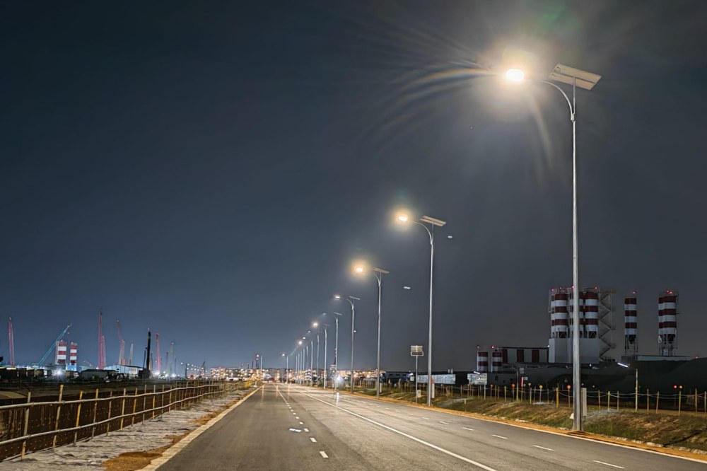
Determine Wind Speed and Cyclone Exposure at the Site
Wind speed is the first number you need to pin down. The design wind speed must match the exact definition in the governing standard. A 3-second gust and a 10-minute average wind are not the same. You cannot compare wind speeds from different standards unless you check their definitions. The 2009 AASHTO LTS-5 wind map gives 3-second gust basic wind speeds in mph. It uses a gust effect factor of 1.14 and a 25-year design life, based on ASCE 7-05. Those values apply to poles mounted at ground level for Exposure C. If a site falls between two velocity isotach lines, use the higher speed.
Gather the full data set before you write any specification. This list covers the least inputs you need:
- Design wind speed and the exact definition used by the governing standard
- Project location and governing structural standard
- Wind-speed averaging period and return period or risk category
- Exposure or terrain category and topographic conditions
- Importance factor, where it applies
- Pole height, mounting arrangement, and complete attachment schedule
- Available soil or foundation information
Regulatory minimums change from place to place. The 2019 US Virgin Islands Code Title 29, Chapter 5 sets a minimum basic wind speed of 145 mph for the whole territory. That region sees about 30 high wind events in 30 years. This includes 13 rated hurricanes and 2 Category 5 events with winds above 157 mph. Special wind regions need extra care. Mountains, gorges, open ocean, and large open land can all make wind speeds that generic maps miss. Always ask the local authority having jurisdiction to confirm the right design wind speed.
Consider Terrain, Coastal Conditions, and Pole Location
Topography changes wind speed a lot. Changes in the land can raise wind speeds by 50–60% above coastal values. A 109 mph coastal wind can become 180 mph inland. A 500-year event may reach 273 mph at some spots. For a 138 mph shoreline wind speed, island-specific exposure shows St. Croix top 20th percentile areas at 175 mph or higher. St. John reaches 184 mph or higher, and St. Thomas hits 192 mph or higher. On St. Thomas and St. John, about 5% of buildings face 200+ mph winds.
Pole shape and fixture placement cut down wind resistance. Round steel poles lower the load profile. Put fixtures at the top of the pole to reduce wind leverage. These choices matter when you specify street light poles for a cyclone-rated site.
For custom projects, work with makers like Morelux. Morelux gives design drawings, structural calculations, wind load analysis, and steel pole solutions made for each project. Their engineering team helps at every stage, from site data review to final paperwork. This approach swaps generic pole-height and wall-thickness tables for engineering built for each cyclone region.
Part 2: Specify Pole Design for Wind Resistance and Loads
Define Wind Load, EPA, Height, and Equipment Loads
Three things set the wind load on a pole: design wind speed, terrain category, and the height wind profile. Wind gets faster as height increases. The top of a 12 m pole has higher stress than the top of a 6 m pole. This difference controls the taper and wall thickness. A taller pole must be stronger than a shorter pole with the same luminaire. Base diameter, wall thickness, and foundation all need to increase with height.
The effective projected area includes every attachment. EPA and dead weight come from luminaires, brackets, tenons, banners, and cameras. Longer outreach arms raise the bending moment because they add leverage. Side-mounted fixtures cause higher moments than top-mounted ones. Make the base moment of resistance 15%–20% higher than the maximum calculated wind load. At maximum wind, the pole top must not move more than 5% of total height. When you specify street light poles, require a signed static wind-load calculation. It must list bending moments, shear forces, and deflection limits.
Select Steel Grade, Pole Shape, and Wall Thickness
Galvanized steel with a modulus about 210 GPa works for poles above 12 m. Wall thickness is usually 3–5 mm for galvanized steel poles. Conical poles work best when wind speeds go above 24 m/s. Round poles lower wind resistance. Vibration control is important too. High-mast systems can use internal dampeners or external strakes. Add vibration dampers if pole shape, luminaire weight, or exposure creates dynamic risk from vortex shedding.
Foundation and anchorage design must fit the soil conditions. Soil bearing capacity should be above 150 kPa. Pick 4–6 high-tensile anchor bolts sized to resist overturning moment. Proper torque prevents base plate fatigue. Helical anchors perform well in weak soils. Concrete poles give low-maintenance hurricane resistance. The upper pole assembly is rated for a certain wind speed and EPA. The foundation, anchor bolts, pole base flanges, and reinforcement must all match that rating. A design life of 25–30 years is typical, and galvanized steel in C3 environments can last 40–50 years.
Part 3: Engineer Foundations and Installation for High Winds
Match Foundation and Anchoring to Site Conditions
The foundation carries every load that the pole receives. Pole height and outreach arm length create the lever arm that causes overturning moment. Design wind speed must be site-specific because base moment grows with wind speed. Coastal cyclone-prone places cannot rely on generic inland table values. Soil conditions decide how much ground resistance fights overturning and uplift. These conditions include bearing capacity, fill, water table, and frost line.
For a pole in a high-wind zone, use a concrete foundation sized for the design wind speed and luminaire load. The foundation dimensions depend on soil conditions; soil bearing capacity should be above 150 kPa. Use a safety factor appropriate for the site and standard. One city rule requires air-entrained concrete from an approved mix, and the concrete must cure to its full design strength before workers erect the pole. Helical anchors work well in weak soils. After Hurricane Ian, investigations found hidden voids in pole bases that reduced capacity. Anchor-bolt torque, grout condition, and backfill compaction must be inspected and recorded.
Specify Corrosion Protection for Coastal Environments
Salt-heavy ocean air can make steel corrode faster than inland air with normal humidity. The zone most likely to corrode is the welded joint where the pole shaft meets the base flange. Hot-dip galvanizing covers outer steel and any inner steel that can be reached. Pay special attention to welds, edges, drainage points, and the base section near ground level. A duplex system of hot-dip galvanizing plus powder coating gives a colored finish for city and architectural projects. Project-specific primers and topcoats work best in coastal or chemically harsh locations. When you specify street light poles for these sites, confirm anchor-bolt material and protective finish before production.
Part 4: Verify Standards, Documentation, and Pole Quality
Check Structural Standards and Engineering Documents
When you pick street light poles for a cyclone-rated site, begin with the standard that controls the project. EN 40 covers European lighting columns. AASHTO LTS-6 covers highway lighting supports. Their wind load methods are not the same; AASHTO uses a 3-second gust map. Check the local code first.
The engineering package must prove the design. Required documents include structural calculations, general arrangement drawings, the attachment and EPA schedule, material certificates, base plate and anchor bolt drawings, welding documentation, galvanizing reports, inspection records, and installation instructions. Welding Procedure Specifications should follow an approved standard. Missing documents are the biggest warning sign. A wind load statement that leaves out accessories does not match field conditions.
Verify Manufacturing, Installation, and Maintenance Requirements
Begin quality checks with raw steel. Mill test certificates trace chemical composition and tensile strength back to the foundry. Steel thickness must match the approved drawing. Wall thickness for galvanized steel poles is typically 3–5 mm. Coastal areas demand wind resistance ratings matched to the site’s design wind speed. Hot-dip galvanizing follows ISO 1461 or ASTM A123, with coating thickness measured. Base flange welds must meet the approved welding specification. Check flange perpendicularity, pole straightness, and pole bending against the approved tolerances.
Installation inspection protects real performance. Anchor bolt alignment must match the template. Anchor bolts should be high-tensile steel as specified. Tighten bolts to the specified torque. Poor torque causes base plate fatigue. Inspect grout and backfill compaction. Grounding resistance should meet the applicable requirement. Follow the installation instructions for lifting, alignment, grouting, and electrical sealing.
Coastal environments need scheduled maintenance. Inspect coatings near welds and edges. Check fastener torque, luminaire mounts, and foundation bolts. The design life is typically 25–30 years, and galvanized steel in C3 environments can last 40–50 years; salt air shortens that span.
Our Engineering and Custom Steel Pole Solutions for High-Wind Projects
Custom Pole Design and Wind Load Engineering Support
Morelux is a custom street light pole maker and supplier for cyclone-rated projects. The engineering team looks at site data before any drawing is made. Project location and the design standard come first. They set wind speed, exposure category, and safety factors. Pole height, shape, material, and wall thickness come next. These set section capacity and deflection. Luminaire, arm, solar panel, camera, and sign details let the team figure out the total effective projected area and top load. Base plate, anchor bolts, foundation, and soil data confirm that wind loads move safely into the ground.
The deliverable package includes EPA calculations that combine projected area with drag coefficient. It also has wind load formulas that follow AASHTO standards, ASCE 7 wind load analysis, and structural analysis software checks. Static load testing finds weak points before installation. Wind tunnel testing copies real wind conditions to measure pole deflection. Contractors get drawings, calculation reports, and test documents to review before production.
OEM & ODM Manufacturing With Quality and Corrosion Protection
Morelux runs OEM and ODM programs from a factory in Malaysia. The factory does cutting, bending, spinning, welding, polishing, powder coating, and anodizing in-house. Quality control follows a fixed order. It starts with a site corrosivity assessment that covers distance to shoreline and splash zone exposure. Substrate prep, weld prep, and edge treatment come next. Galvanizing follows ISO 1461 or ASTM A123, with measured coating thickness instead of a certificate alone. Duplex coating compatibility, fastener choice, and base drainage details are checked before shipment. Mill certificates, coating reports, and warranty terms go with every order. All poles are designed and tested to applicable AASHTO and EN 40 specifications.
A street light pole built for cyclones is a whole-system choice, not something you pick from a catalog. The pole shaft by itself will not hold up if the foundation, anchors, or attachments are too weak. Before you approve anything, check these items: design wind speed (at least 145 mph where codes require it), the effective projected area of all fixtures, pole shape and wall thickness, material and corrosion protection, foundation and anchorage, vibration control, and supplier paperwork. Ask for stamped structural calculations for the whole assembly. Look over the poles when they arrive, before installation, and check anchor bolt torque and grout condition. Make sure the base flange and anchor bolts match the pole’s wind rating. For upkeep, mild inland sites can wait longer between checks, but coastal hurricane zones need frequent inspections, plus a check after every strong wind.
Frequently Asked Questions About High-Wind Street Light Poles
Is a Pole’s Allowable EPA the Same at Every Mounting Height?
No. Allowable EPA can vary with mounting height because height affects wind exposure and overturning forces. Pole height, wind speed, exposure, fixture EPA, and mounting configuration should be evaluated together during structural design.
How Should Street Light Poles Be Rated for Cyclone Winds?
Cyclone-rated street light poles should be designed based on site wind speed, exposure, fixture loads, pole geometry, and applicable standards. MORELUX uses structural design software to assess wind and fixture loads in line with AASHTO, BS EN 40, AS/NZS, and MS specifications.
Can Solar Street Light Poles Be Used in High-Wind Regions?
Yes, when the pole, solar panel, brackets, luminaire, and foundation are designed for the required wind loads. Solar panels add projected area, so their loads should be included in the structural assessment. MORELUX provides customized steel solar lighting poles for different project requirements.
What Documents Should You Request From a Pole Manufacturer?
Request structural calculations, wind load analysis, technical drawings, material specifications, and compliance information. Pole dimensions, wall thickness, mounting details, foundation requirements, and corrosion protection should also be confirmed before production.