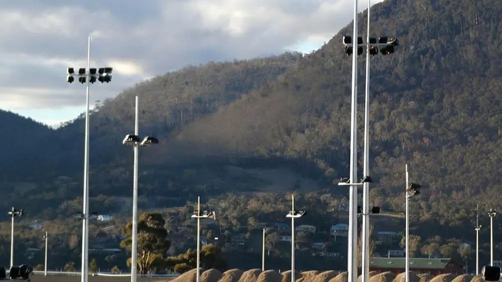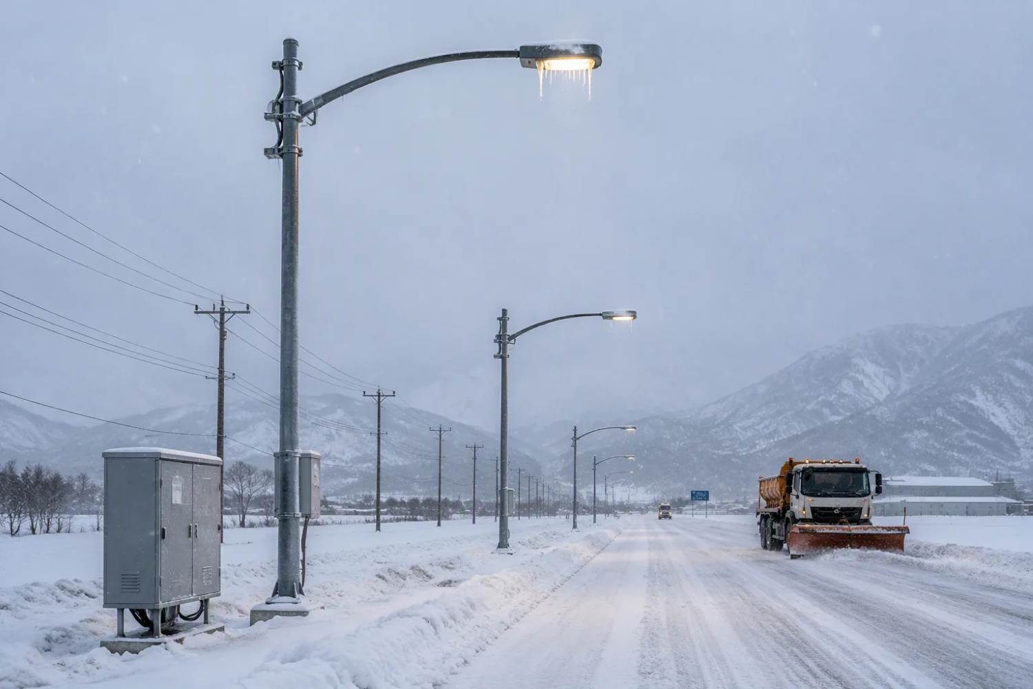

Three steps are key to every successful light pole installation. First, drill the hole to the right depth and width. Second, set the base plate level and secure it. Third, fill and pack the soil or concrete around the foundation. A level base spreads the pole’s weight evenly across the ground. Correct sizing keeps the structure straight under wind and vibration. Poor preparation shows up later as leaning poles, loose anchor nuts, and costly rework. This guide explains measurements, anchor bolt hardware, installation methods, base material comparisons, and jobsite safety. Readers can then plan the work with confidence and avoid common mistakes.
Key Takeaways
- Do these three steps: drill the hole, make the base plate level, and fill in dirt around the foundation.
- Get your tools and materials ready before you dig. This saves time and helps you avoid mistakes.
- Use a template to keep the anchor bolts lined up, and check how far the bolts stick out right after you pour the concrete.
- Use nuts and washers to make the base plate level, then tighten the nuts to hold the pole in place.
- Check the base often and connect the equipment grounding wire for safety.
Essential Tools and Materials for Light Pole Base Installation

Every base installation follows the same three steps. First, auger the hole. Second, place the base. Third, backfill around it. The hole is usually round and several feet deep. Match the depth and width to the pole height and the local code. A taller pole needs a deeper, wider hole. Confirm the final dimensions with the project engineer before digging.
Good preparation saves time on site. Pre-level the anchor nuts on the anchor bolts. Confirm the anchor bolts are aligned with the base plate pattern. Tape the wires together before lifting the pole. Stage each pole in an accessible spot for easier rigging. These small habits prevent delays during the lift.
Backfill material should follow project requirements. Crushed stone or granular fill such as sand works well for light pole bases. Apply it uniformly in 6 to 8-inch lifts. Compact each lift to 95% standard proctor density. Install conduits through the side openings before finishing backfill to final grade.
Precast bases follow a slightly different sequence. Backfill to just below the large side openings. Run the conduits through the openings and out the top. Then place the base. Each base ships with a complete hardware set. Nuts, washers, and anchoring rods come in the box. Bolt circle diameters from 7.5 to 13.5 inches are accommodated, so no separate J-bolts are needed.
A basic tool kit covers most jobs. A trailer ball wrench or combination box-end wrench tightens the nuts. Two magnetic bullet levels help check the base plate. Proper lifting straps, slings, and rigging equipment handle the pole safely. A cordless impact wrench with deep sockets speeds up bolt work. A pipe wrench, wire wheel, and angle grinder support adjustment and cleanup. New light pole hardware and a rust-encapsulating coating complete the kit.
Larger equipment depends on the task. An auger truck or excavator with an auger attachment digs the hole. Trenching equipment such as a Ditch Witch cuts the conduit path. An excavator, loader, or Skytrak lifts and sets base units. A standard level, laser level, or transit level confirms a level base. Shovels, rakes, and hoes handle final grading.
| Category / Purpose | Tools & Materials |
|---|---|
| Digging & hole preparation | Auger truck or excavator with auger attachment |
| Trenching for conduit | Trenching equipment (e.g., Ditch Witch) |
| Lifting & setting base units | Excavator, loader, or Skytrak; skid-steer loader; Pole Base lifting plate and chains |
| Ensuring level bases | Standard level, laser level, or transit level |
| Final grading | Shovels, rakes, hoes |
| Safety gear (PPE) | Hard hats, gloves, safety glasses, high-visibility vests |
Safety gear belongs on every job. Hard hats, gloves, safety glasses, and high-visibility vests protect the crew. Steel pole base plates and flange designs from suppliers such as Morelux arrive ready for these standard tools. A complete kit and a clear plan keep the installation smooth from the first dig to the final check.
Site Preparation and Foundation Requirements for Light Pole Bases
Pole Specifications and Foundation Design Before Installation
Foundation design starts with the pole itself. Height, wall thickness, fixture weight, and fixture EPA all feed the structural calculation. Modern codes model the pole as a cantilever fixed at ground level, then size the footing so soil pressure stays within allowable bearing capacity and safety factors for overturning and sliding are met. A qualified structural engineer must check and approve the final design under local rules.
Planning references by pole height help early budgeting. A 6–8 m pole may use a direct-embed or spread footing around 600×600×900 mm to 800×800×1200 mm. A 9–10 m pole typically moves to a spread footing with anchor bolts, roughly 800×800×1200 mm to 1000×1000×1500 mm. Poles of 11–12 m and 14–15 m scale up further, and anchor bolt diameter and embedment become critical. Confirm every dimension with an engineer using site wind speed and soil data.
Anchor bolt projection is the length of bolt left above the concrete. It must match the base plate thickness, leveling nuts, and top nuts. Too little projection leaves no room to level the plate. Adjustable anchor nuts solve this. Set them below the plate, fine-tune the plate after the concrete sets, then clamp with top nuts. A typical kit includes 4–8 anchor bolts on a bolt circle matching the plate holes, leveling and top nuts, a rebar cage, hot-dip galvanized bolts with protected threads, a rigid template, aligned conduits, and grounding hardware.
Site Layout, Base Positioning, and Underground Conduit Planning
Layout work begins before any digging. Confirm permits, including electrical permits, zoning compliance, and underground utility clearance through 811. Assess soil type, drainage, and frost depth. Loose or saturated soils may need a deeper embedment or an engineered alternative. Keep poles out of the clear zone where possible, and use breakaway poles near traffic with a safe falling area.
Conduit planning deserves the same care. Most bases receive two conduits, one in and one out, since each light pole acts as a junction point. The end-of-run pole gets one. Run a spare where budget allows. Bury conduit at least 24 inches to the top, per NEC Table 300.5, and leave stubs long for trimming at pole set. Cap and tape every conduit, then verify geometry with the template on the actual bolts before pouring.
Anchor Bolt Placement and Alignment for Light Pole Base Plates
Using an Anchor Bolt Template to Maintain the Correct Bolt Pattern
A strong template keeps the anchor rods in place while the concrete hardens. The aluminum template goes over the rods before the pour. It holds every bolt at the right spacing, so the base plate slides over the finished pattern without force. Use the steel template that comes with the anchor bolt set. It fits the pole base and keeps the correct pattern.
Set the template level and plumb on both axes. Tilted bolts stop the base plate from sliding down. Check the template direction as well. The wiring access opening must face the electrical feed direction. A turned template puts the wiring hole away from the conduit. Tell the concrete crew the layout clearly. Say “10-inch bolt circle” instead of a vague “10-inch pattern.” This habit stops a mismatch between poured bolts and the base plate.
For precast units, mark the base location first, then auger or dig and trench for the conduit. Install the foundation and place the base. Confirm all sizing with local code or an engineer.
Checking Anchor Bolt Projection, Spacing, and Vertical Alignment
Projection is the thread length left above finished concrete. Measure it against the manufacturer’s spec right after the pour, while the concrete is still workable. Bolts set too deep cannot be raised. Too little projection leaves the nut short of the threads needed to build clamping force.
Inspect the existing footing before any drilling work. Major cracking, spalling, or damage around old bolts points to a structural problem. New anchors do not fix a weak footing. Confirm the drill size, embedment depth, and edge distance from the engineered drawing, not from rules of thumb. A shallow pilot hole stops the bit from walking. Clean each hole well before setting adhesive, and let it cure fully before loading the light pole.
Concrete Pouring and Curing for Reliable Light Pole Foundations
Two installation methods are used most often in the field. Bolt-down construction uses a concrete foundation and anchor bolts. Direct burial puts the pole itself in the ground. Bolt-down works well for tall poles, heavy fixtures, and sites where the pole may need to be replaced. It gives the strongest hold and makes future service easy, though it costs more and takes longer to cure. Direct burial works well for shorter poles, lighter loads, and projects with a tight budget. It installs fast and needs no anchor hardware, but removal and realignment are hard. Neither method is better in every case. Match the choice to pole size, load, soil, and budget.
Concrete Placement and Consolidation Around Anchor Bolts
Ready-mix concrete should meet the required compressive strength. Standard light pole foundations usually call for at least 3,000 psi (20 MPa) at 28 days. Place the mix in lifts and consolidate each one with a vibrator. This step removes voids around the anchor bolts and the reinforcing rebar. Dense, void-free concrete grips the bolts fully and carries load without settlement. If you skip consolidation, air pockets weaken the embedment.
Maintaining Foundation Level and Allowing Adequate Concrete Curing
Level control starts before the pour. Build sturdy bolt templates from 1/2-inch plywood instead of flimsy masonite. Drill the holes tightly so the assembly cannot shift. Pour slowly and watch the conduits and rebar stay plumb and centered. Adjust level as the tube fills. Tap the form to release trapped air. Finish the concrete while it is still workable.
“A concrete guy told me the trick was to finish them ‘hot.’ You need to strip the forms at just the right time. The concrete will be set enough not to fall apart but still workable. The timing is something you have to learn. It depends on the slump and the weather.”
Curing protects strength gain. Test the mix at placement with a slump test, an air content check (usually 5–7% for exterior freeze-thaw concrete), and temperature and unit weight readings. Cast at least four cylinders per sample: one for 7-day testing, two for 28-day testing, and one spare. Confirm the 28-day compressive strength meets spec and keep batch tickets on file. Common defects trace back to causes you can prevent. Plastic shrinkage cracks follow rapid surface drying, so add wind protection, fog misting, and immediate curing. Scaling points to poor air entrainment or finishing over bleed water. Dusting results from added water or insufficient curing. Proper mix design and timely curing prevent all three.
Base material affects long-term performance. Steel base plates resist high wind loads and heavy fixtures, and hot-dip galvanizing adds corrosion resistance for outdoor service. Composite bases resist corrosion in coastal or chemical environments and weigh less, which makes handling easier. Steel fits high-load infrastructure work; composite fits moderate loads and harsh exposure. Morelux, a Malaysian manufacturer and supplier of steel poles, offers custom base plates and flange designs for wholesale projects. Confirm the material choice with the project engineer.
Light Pole Mounting, Base Plate Leveling, and Final Alignment
Aligning the Base Plate With Anchor Bolts and Leveling Nuts
The base plate never rests directly on concrete. A stack of hardware carries the load and allows adjustment. Read the stack from the bottom up:
| Layer | Component | Function |
|---|---|---|
| 1 | Anchor bolt | Embedded anchorage in the footing |
| 2 | Leveling nut | Supports and adjusts the plate from below |
| 3 | Washer | Spreads load beneath the plate |
| 4 | Base plate | The pole’s mounting plate |
| 5 | Washer | Spreads load above the plate |
| 6 | Top nut | Secures the plate to the bolt assembly |
This stack keeps a metal-to-metal connection. A plate set straight on concrete lets wind movement wear the surface, and the hardware loosens over time.
Mounting follows a fixed order. Attach a sling to the top of the pole, fit the luminaires and wiring, then thread the leveling nuts and washers onto the bolts. Raise the pole and lower it onto the leveling nut washers. Never stand a pole without its intended loading attached. Keep the bottom of the lowest nut no more than one inch above the concrete. A larger gap raises stress on the anchor bolts.
Anchor Nut Tightening, Pole Plumbness, and Final Position Checks
Tighten the bottom nuts against the plate first, then the top nuts. Apply roughly 45 lb-ft of torque, or tighten firmly with a box-end wrench using both hands. Verify every nut the same way.
Check plumbness with a spirit level on the top plate, north-south and east-west. Start north-south: raise the bottom nut on the low side until the plate is level, then tighten the top nuts on those bolts. Repeat east-west for final alignment.
Return on a schedule. Check bolt tightness, plate condition, corrosion, and drainage around the base. On site, inspect rigging before every lift, keep the open hole covered, and treat wiring as live until proven otherwise.
Light Pole Foundation Inspection and Electrical Grounding Requirements
Concrete Strength, Anchor Bolt Alignment, and Base Level Checks
Inspection happens in steps, not just once at the end. Check the anchor bolt template before the pour and again after it. Watch the bolts while the concrete is still soft. A bolt that moves now will stop the base plate from fitting later, and the fix means re-drilling or re-pouring. Level the template vertically before you secure it. Make sure the top of the base is perfectly level while the concrete is still workable. Even a small tilt can make the pole lean.
Concrete strength decides when the pole can go up. Mounting too early causes cracking, bolt movement, and an unstable base. Keep the concrete damp for 7 to 14 days of curing. Test the cure strength if the schedule is rushed.
| Aspect | Risk | Action |
|---|---|---|
| Anchor bolt alignment | Base plate will not fit | Fix a rigid template at the correct depth; verify before and after pouring |
| Concrete strength | Cracking and bolt movement | Cure 7–14 days damp; test strength if rushed |
| Base level | Pole leans | Level the template vertically before securing |
Inspect the finished foundation on a schedule. Check bolt tightness, plate condition, corrosion, and drainage every year. Coastal sites with salt exposure need checks every six months. Re-torque loose bolts. Replace the foundation if the concrete is cracked through, the bolts are unsafe, or the pole is out of plumb.
Grounding, Bonding, and Electrical Connection Requirements
The National Electrical Code treats a metal lighting standard as a pole over 12 ft tall, measured from the bottom of the base or the intended grade level. A common grounding detail uses a 1/2 inch by 10-foot copperweld ground rod driven in the center of the base and sticking up slightly above it. As another electrode option, the code accepts 20 feet of bare, zinc-galvanized, or conductive-coated steel reinforcing bar at least 1/2 inch in diameter. The bonding jumper must be no smaller than No. 8 copper or No. 6 aluminum.
An equipment grounding conductor (wire or metal raceway) must be bonded to the metal pole, to clear line-to-ground faults. The anchor bolts, reinforcing rod, and concrete may provide a good ground, but this does not remove the requirement to install and bond an equipment grounding conductor.
Connect both the ground rod and the equipment grounding conductor to the metal standard. Treat every light pole circuit as live until it is proven otherwise.
Several things decide the final design. Think about ground conditions, pole size and load, installation method, base material, and local code rules all at once. No single factor works alone. Soft soil may need a deeper footing. A tall pole with heavy fixtures may work better with bolt-down construction. Coastal exposure may point toward galvanized steel or composite.
The three-step process is still the backbone of every light pole base job: auger the hole, place the base, backfill around it. Good preparation at each step stops rework later. For complex projects, unusual soil, or large poles, ask a qualified specialist or engineer before digging.
Frequently Asked Questions About Light Pole Base Installation
What Determines the Required Depth of a Light Pole Foundation?
Light pole foundation depth depends on pole height, fixture weight, wind loads, soil conditions, and local design requirements. Taller poles or those supporting multiple fixtures may require a more substantial foundation. Structural calculations and site assessments should determine the final dimensions.
How Long Should Concrete Cure Before Light Pole Installation?
Concrete curing time depends on the mix design, temperature, and site conditions. Light pole installation should proceed only when the foundation reaches the strength specified in the structural design. Follow the engineer’s recommendations before erecting the pole or applying loads.
What Keeps Anchor Bolts Properly Aligned During Concrete Pouring?
An anchor bolt template or positioning frame helps maintain the correct bolt spacing, orientation, and projection above the concrete. Check the layout against the pole base plate drawings before pouring, and ensure the bolts remain stable during concrete placement.
Should a Light Pole Base Plate Sit Directly on Concrete?
Not necessarily. Depending on the engineered design, the base plate may require leveling and non-shrink grout beneath it to provide uniform bearing. Follow the approved drawings for base plate elevation, anchor bolt installation, grout placement, and tightening requirements.